
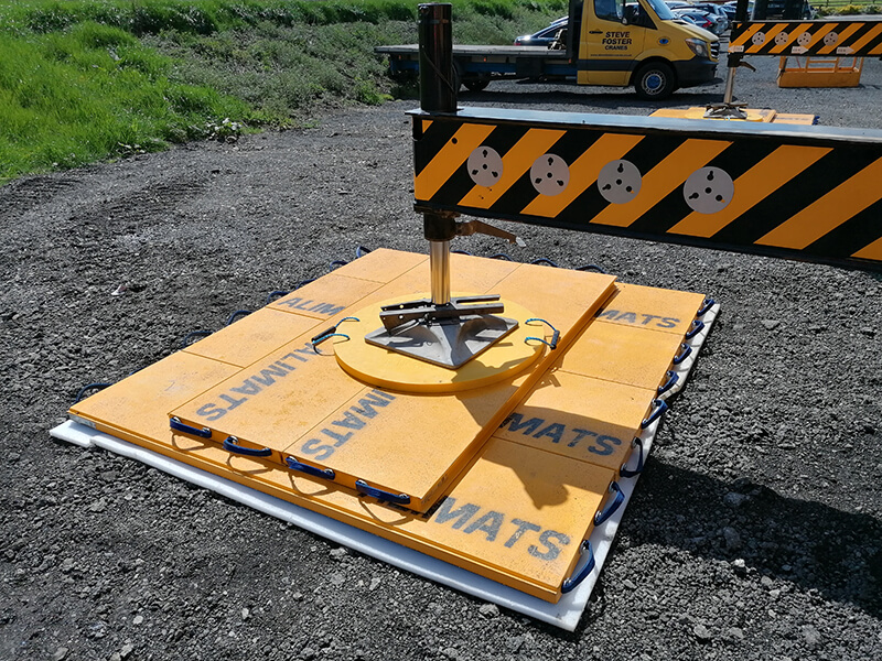
Every crane mat, outrigger pad and stabiliser mat we make exists to answer one question: given a known force pressing down at a single point, and a known amount of pressure the ground beneath can safely take, how much contact area do you need to keep the two within limits of each other? That is the whole calculation — one division sum — but it has enough moving parts feeding into that sum, and enough ways for an unstated assumption to creep in, that we think it earns a proper walk-through rather than the single line most pages give it.
So here is the method in full — the bearing pressure formula and its units, where the force side comes from, where the ground side comes from, what happens to the load as it spreads through a layer of fill on its way down to weaker ground, and why a mat's own stiffness decides whether the number you calculate actually holds on site. We have written it for the temporary works engineers, appointed persons and specifiers who want to follow the reasoning themselves rather than take an answer on trust.
The basic bearing pressure formula
The core relationship is pressure equals force divided by area — the same idea as a drawing pin, which presses far harder through its point than through its flat head for the same thumb behind it. Rearranged to solve for what a mat has to provide, it becomes area = force ÷ allowable bearing pressure. Get the force and the allowable pressure right, and the area you need falls straight out.
Units matter here more than the arithmetic does, because getting them wrong is the easiest way to be out by a factor of ten and never notice. Force is usually an outrigger or leg reaction, given in tonnes-force or kilonewtons (kN) — and if it arrives in tonnes, convert it to kilonewtons before dividing, because 1 tonne-force is roughly 9.81 kN. Allowable bearing pressure is conventionally quoted in kilopascals (kPa), which is numerically identical to kilonewtons per square metre (kN/m²) — the same quantity written two ways, so do not be thrown by seeing it either way. Divide a force in kN by a pressure in kN/m² and the answer comes out in square metres: the footprint the mat has to cover.
A worked example. Read an outrigger reaction off the crane's load chart at, say, 50 tonnes-force, and take an allowable bearing pressure of 100kPa confirmed by site investigation. Convert the force first: 50 tonnes x 9.81 = 490.5kN. Then divide: 490.5kN ÷ 100kPa = 4.905m². That is the minimum contact area needed under that outrigger to hold ground pressure at or below 100kPa. On a real job we would choose a mat configuration that clears that figure with a sensible margin rather than size it to the last decimal — the round numbers here are picked to show the method cleanly.
| Symbol / term | What it represents | Typical unit | Where it comes from |
|---|---|---|---|
Force (F) | Reaction at the specific leg, track or stabiliser being checked | kN (convert from tonnes-force x 9.81) | Plant manufacturer's load chart, or a competent person's derived calculation |
Allowable bearing pressure (q) | Pressure the ground can safely sustain without excessive settlement | kPa (= kN/m2) | Site investigation, or a competent assessment where none exists |
Required area (A) | Minimum contact footprint needed to keep pressure within q | m2 | Calculated: A = F ÷ q |
Spread angle (through fill) | Simplifying assumption for how load widens with depth through granular fill | Ratio, e.g. commonly illustrated around 1 horizontal to 2 vertical | Geotechnical engineer's confirmation for the specific fill material, not assumed |
Deflection | How much a mat bends under the applied load | mm | Manufacturer test data on a representative rig and base |
Symbol / term:
What it represents:
Typical unit:
Where it comes from:
Symbol / term:
What it represents:
Typical unit:
Where it comes from:
Symbol / term:
What it represents:
Typical unit:
Where it comes from:
Symbol / term:
What it represents:
Typical unit:
Where it comes from:
Symbol / term:
What it represents:
Typical unit:
Where it comes from:
Where the force comes from
The force half of the equation is the reaction at the specific leg, track or stabiliser you are checking — and it is very rarely an even share of the plant's total weight. A crane's four outriggers do not carry a quarter each. The leg nearest the load and nearest full radius takes far more than the others, and which leg that is shifts as the boom slews through the lift. Our mobile crane outrigger mats guide sets out the reasoning behind that uneven split in detail; the short version is that the reaction at the most heavily loaded leg, at the radius and slew the lift plan calls for, is the figure that belongs in this calculation — never the crane's rated capacity divided by the number of legs.
That reaction should come from one place: the plant's own manufacturer load chart or duty chart, read at the actual radius, boom configuration and outrigger extension the lift plan specifies — or, where the geometry is more involved than a straight chart lookup, a competent person's calculation derived from it. Never estimate it by eye, round it from memory, or assume it carries over from a similar-looking crane on a previous job. The same principle holds well beyond mobile cranes: a concrete pump's stabiliser reaction, a piling rig's track pressure and a crawler crane's track reaction are all plant-specific figures that drop into this same slot in the formula, sourced the same way.
Where the allowable bearing pressure comes from
The other half of the equation — what the ground can actually take — deserves at least as much care as the force side, and in practice it is the half more often guessed at. The gold standard is a genuine site investigation: trial pits, plate bearing tests or borehole data interpreted by a geotechnical engineer, giving an allowable bearing pressure for the actual ground, at the actual location, in the condition it will be in on the day the plant stands on it. Ground is not uniform across a site and it does not stay fixed over time — made ground compacted last month may not have finished settling, and ground that was bone dry during the survey can behave very differently after a week of rain.
Where a full investigation isn't available, published reference ranges do exist for broad ground categories, and the direction of travel is obvious enough: soft, disturbed or made ground carries a far lower safe bearing pressure than well-compacted granular fill, and rock or established hardstanding sits higher again. But a specific kPa figure pinned to a named soil type in a generic table is a broad illustrative range at best, and it still needs site-specific confirmation before anyone designs against it — ground that looks identical on the surface can behave very differently a metre down. In our view, a number lifted from a table rather than from an assessment of the real site is a guess wearing the clothes of a calculation. Where no investigation exists yet and you only need an indicative starting point, our own Ground Bearing Capacity Calculator gives a first-pass figure to work from — a starting point, not a stand-in for a proper site investigation or a competent person's sign-off on anything safety-critical.
How the load spreads through the fill below
So far the calculation treats the mat's footprint as the area the ground pressure acts over. At the surface, directly under the mat, that is exactly right. But where a mat sits on a layer of granular hardstanding or compacted fill with weaker ground beneath, the load does not stay boxed into the mat's own dimensions as it travels down. It spreads outward through the fill, so by the time it reaches the weaker layer below it is acting over a larger effective area than the mat's footprint alone would suggest.
The principle is straightforward — a granular fill layer distributes a point load outward as well as downward, in a shape often simplified in temporary works guidance as spreading at a set angle from vertical, commonly drawn as something around 1 horizontal to 2 vertical, though other guidance uses other ratios depending on the fill assumed. It is a modelling convenience that lets a designer estimate the effective bearing area at the top of the weaker layer without running a full geotechnical stress analysis. It is not a fixed law that applies identically to every fill and every depth. The true spread angle depends on the fill's grading, compaction and depth, and for anything safety-critical that is a geotechnical engineer's call, not a figure to lift from a diagram.
In practice this means a thin layer of well-compacted granular fill under a mat can meaningfully cut the pressure reaching genuinely weak ground further down, compared with the same mat sitting straight on that weak ground with no fill at all — which is why we treat hardstanding preparation as part of the ground engineering rather than a lesser concern alongside the matting decision. But it only works in the direction the calculation assumes if the fill is properly compacted and thick enough for the spread to actually develop. A thin, poorly compacted layer over soft ground will not deliver the spread a textbook diagram implies.
Stiffness: whether the calculated area is actually delivered
There is a second condition buried in the area calculation, and it is easy to miss: the sum only holds if the mat itself stays flat and rigid under load. Area = force ÷ allowable bearing pressure assumes the mat is in full, even contact with the ground across its whole stated footprint, spreading the point load evenly to every part of it. A mat that deflects significantly stops doing that. Instead of a flat panel pressing evenly, it bends into a shallow bowl — hardest directly under the load, tapering off toward the edges — and the ground beneath is no longer feeling anything like the evenly spread pressure the calculation assumed.
We cover this in full, with independent test data, in our aluminium versus plastic bending test, so we will not re-derive it here — but the underlying point is simple. A mat's safe working load rating tells you the load it survives without breaking; it tells you nothing about how far it bends below that load. Two mats can carry an identical rated tonnage on paper and behave completely differently on the ground — one staying essentially flat, the other dishing noticeably — because strength and stiffness are different properties. The area our formula produces is only the area a mat needs to cover. Whether a given mat actually delivers full-footprint contact at that area, rather than quietly narrowing back down toward the size of the outrigger foot itself, comes down to how stiff it is under the load in question.
The calculation, step by step
Pulled together, the whole sequence runs like this. First, establish the actual reaction at the specific leg, track or stabiliser you are checking, at the radius and configuration the lift plan specifies, from the manufacturer's own load chart or a competent person's derived calculation — never an even split of total plant weight. Second, establish the allowable bearing pressure for the actual ground at the actual location, ideally from a site investigation and at minimum from a competent assessment, treating any generic published range as a starting point that still needs site-specific confirmation. Third, divide the reaction by the allowable bearing pressure — converting units carefully — for the minimum required contact area. Fourth, where the mat sits on a fill layer over weaker ground, check whether load spread through that layer needs accounting for separately, and if so get a geotechnical engineer to confirm the actual spread angle rather than assuming a textbook one. Fifth, choose a mat whose footprint clears the required area with a sensible margin and whose safe working load clears the reaction. Sixth — the step most often missed — confirm the mat is stiff enough not to deflect meaningfully under that load, because a mat that dishes is not delivering the full-footprint contact the area calculation assumed. Then have the whole sequence checked and signed off by a competent person as part of the site's temporary works process.
Why this is a competent person's calculation
None of this is proprietary to us or unique to any one mat manufacturer — it is standard, well-established structural and geotechnical engineering. But standard maths applied to the wrong input still produces the wrong answer with total confidence, and the two inputs most likely to be wrong on a real site are exactly the two we keep coming back to: the outrigger reaction at the actual working radius, and the allowable bearing pressure of the actual ground on the day. Both belong to manufacturer data and a genuine site assessment, not to an estimate or a generic table.
We set the method out in this much depth so that a specifier, appointed person or project engineer receiving a mat recommendation can follow the reasoning behind it, ask the right questions of whoever produced the numbers, and spot when a figure has been assumed rather than established. A definitive design for anything safety-critical — a heavy lift, a piling rig, ground with a known history of poor bearing capacity — still belongs with a qualified temporary works engineer working from a real site investigation. Understand the principles here, use them to sanity-check what you are handed, and bring us in early on the matting once the inputs are sound.
Frequently asked questions
What is the basic formula for calculating crane mat size?
Required area equals the applied force divided by the ground's allowable bearing pressure — area = force ÷ bearing pressure. The force is the actual outrigger, track or stabiliser reaction at the leg you are checking, and the bearing pressure is what the specific ground on site can safely sustain. Both have to be established properly before the division means anything.
What units should I use for this calculation?
Convert force to kilonewtons — multiply tonnes-force by roughly 9.81 — and take allowable bearing pressure in kilopascals (kPa), which is numerically the same as kilonewtons per square metre (kN/m²). Divide a force in kN by a pressure in kN/m² and you get an area in square metres directly. Mixing tonnes with kPa without converting is the most common way to end up an order of magnitude out.
Where do I get the outrigger reaction figure from?
From the crane or plant's own manufacturer load chart or duty chart, read at the actual working radius, boom length and outrigger extension the lift plan specifies, or from a competent person's calculation derived from it. Never estimate it as an even share of total plant weight — individual legs carry very unequal shares depending on load position and slew angle.
Can I use a generic table of soil bearing pressures instead of a site investigation?
Only as a rough starting point, never as a design figure. Published ranges for ground categories are broad and illustrative, and real bearing capacity depends on a site's compaction, moisture and history, which vary significantly even across ground that looks identical on the surface. A genuine site investigation, or at minimum a competent person's assessment, is the only reliable source for a figure to design against.
What does "load spread through depth" mean, and does it change the mat size I need?
It refers to how a load widens out as it travels down through a layer of granular fill or hardstanding before it reaches weaker ground beneath, which means the effective bearing area at that depth can be larger than the mat's own footprint. It is a genuine effect used in some temporary works guidance, but the actual spread angle depends on the specific fill and should be confirmed by a geotechnical engineer, not assumed from a rule of thumb.
Is a 1-horizontal-to-2-vertical spread angle always correct?
No. It is one commonly cited simplifying assumption from some good-practice guidance, not a universal constant. The real spread angle through any given fill depends on its grading, compaction and thickness, and for anything safety-critical it needs confirming by a geotechnical engineer for the actual fill in question rather than taken as fixed.
Why does mat stiffness matter if the area calculation already gives me the right footprint?
The area calculation assumes the mat stays flat and gives even contact across its full footprint. A mat that deflects significantly bends into a shallow bowl instead, concentrating pressure back down under the load rather than spreading it — so the calculated area is not actually being delivered on the ground, however sound the arithmetic. We cover this in detail, with independent bending test data, in our separate aluminium versus plastic crane mats guide.
Is there a quicker way to get an indicative bearing pressure figure before a full site investigation is arranged?
Our Ground Bearing Capacity Calculator gives an indicative starting estimate to work from. It is a useful first pass for early planning, but it is not a substitute for a genuine site investigation or a competent person's sign-off where the calculation is safety-critical.
Does this calculation apply to plant other than mobile cranes?
Yes. The same force-over-bearing-pressure method applies to any concentrated point load reaching the ground through a limited contact area, including concrete pump stabiliser legs, piling rig tracks and crawler crane tracks. What changes is where the reaction figure comes from and how it is distributed, not the underlying formula.
Who should actually sign off a crane mat sizing calculation for a live job?
A competent person, as part of the site's temporary works process, working from a real site investigation and the plant's genuine load chart data — not a generic article, a rule of thumb or a calculation run without site-specific inputs. Understand the method, sanity-check what you're handed against it, and bring in that sign-off before the mats go out.